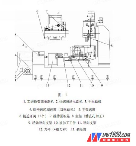
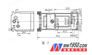
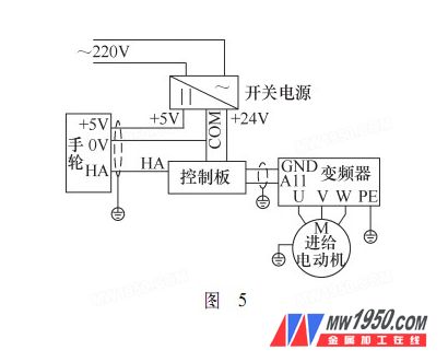
Author: Shandong Lunan Machine Tool Co., Ltd. Wang Shao, Cheng Xiantong Zaozhuang Daxing Mining Co., Ltd. Zhang Haixia The boring method is a highly precise, efficient, and cost-effective technique used for machining box hole systems. It is widely applied in industrial production. Each company customizes its own specialized boring machine tools based on specific requirements. This article introduces the model plane designed for the lifting and sliding seat processing of our G62 milling machine. The author highlights the innovative ideas, technologies, and techniques incorporated into the design and manufacturing process. This equipment is a combined die plane (see Figure 1), capable of machining both horizontal and vertical hole systems in one clamping operation, significantly improving production efficiency. It supports semi-automatic operation—after completing the horizontal hole system, simply pressing the fast forward button will automatically move to the vertical hole processing position. The positioning accuracy remains within 0.01mm. The transmission system and components are optimized for cost-effectiveness, allowing for stepless speed control during work feed. One of the most notable features is the integration of an electronic pulse generator on a standard electrical control system (non-CNC) at a low cost. (1) Die Design: Based on the structural characteristics of the machined parts, a thorough process and structural analysis were conducted to determine the optimal process plan. This included the design of the positioning structure, clamping mechanism, tool holder setup, and multi-axle box configuration. Figure 2 shows a schematic view of the workpiece being processed. From the structural analysis, the positioning is based on reference points A and B. The overhang for holes II, III, and IV is relatively small, so the die layout was chosen as "single-sided rear guide." The guide bracket 11 is placed behind the cutter, and the cutter rod 12 is rigidly connected to the multi-axle box 13 via a Morse cone. For the I-axis, where the two holes are far apart and the end hole has a closed surface, a "fixed and suspended guide combination" was selected. The fixed guide bracket 11 is stationary, while the movable guide bracket 9 can slide in and out through the workpiece's process hole (265 mm × 415 mm). This design contributes to a more compact machine tool structure. To ensure die accuracy and simplify assembly, the two guide bracket holes on the I-axis were machined simultaneously. The remaining guide bracket holes were rough-machined and left for final processing. After assembling the multi-axle box, the appropriate tools were installed, and the I-axis was aligned. The rest of the die-supporting holes were then machined by the machine itself. This approach has proven to be fully feasible in practice. (2) Work Feed Transmission System Design: As shown in Figure 3, the system includes one fast feed motor 1 for rapid movement, one frequency-variable motor 2 for industrial feed and micro-feed (with stepless speed control), and an electromagnetic clutch 3 in the worm and worm gear reducer for switching between fast feed and work feed. The reducer is connected to a lead screw that drives the slide movement. When moving quickly to the vertical hole machining position, two proximity switches 6 (see Figure 1) are used to stop the movement. When the first switch activates, the fast feed motor stops, and after a short delay, the electromagnetic clutch is engaged. By setting a suitable slow speed, the second proximity switch triggers to complete the accurate positioning. The use of two proximity switches helps eliminate large positioning errors caused by inertia during high-speed movement. The method of fast followed by slow ensures accurate positioning, while the delay prevents damage from rapid clutch switching. Testing has confirmed that this control method achieves a repeatable positioning accuracy of 0.01mm. (3) Application of Handwheel Electronic Pulse Generator: To improve tool setting accuracy and facilitate blind hole boring, we redesigned the manual hand drive mechanism to reduce labor intensity. We developed a hand pulse signal circuit board that converts the pulse signal into an analog voltage, enabling micro-feed functionality on ordinary electric-controlled machines at a very low cost. Working principle: The control board is powered with +24V, and the VI point receives the pulse signal from the manual pulse generator. The signal is converted into a 0–10V analog voltage using a circuit composed of components like the LM337 module. The rotation speed of the handwheel determines the output voltage, which in turn controls the speed of the feed variable frequency motor via the frequency converter. This allows the axial movement speed to match the handwheel rotation speed, making micro-feed operations much more convenient. The direction of feed is controlled by selecting either the X-axis or Y-axis on the handwheel’s electronic pulse generator. These selections are connected in series to the interlock control circuit, allowing the feed to advance or retreat accordingly. The circuit control board’s working principle is illustrated in Figure 4, and the basic connection diagram is shown in Figure 5. After the special machine was put into use, the machining accuracy of the workpiece fully met the design specifications, and the overall efficiency saw a significant improvement. The handwheel electronic pulse generator performed well and has been patented, offering a viable solution for upgrading traditional machine tools. The double proximity switch positioning method and control strategy can also be adapted for use in other special machine tools. This project provides new design insights for future development of our customized machine tools.
The 20V 2Ah 4Ah Cordless Plunge Cut Track Saw is Perfect for Cutting Wood, with High Precision, No burrs with good blade.
It is a Cordless wood cutting power tools that users feels much better, compared to Jig Saw or circular saw.
The Cordless Plunge Cut Saw with 30mm cutting depth without track.
The Cordless Plunge Track Saw With single speed, 4000rpm.
The 110mm Cordless Track Saw with Shaft Lock, for easy blade change.
Cordless Power Saw With a dust blower for max cut -line visibility.
Cordless Wood Cutting Power Tools with protection button for your safety, soft rubber handle for comfortable use.
The Cordless Tack Saw used with the Guide Rail or Track, to ensure the cutting straight ability for long distance work.
Plunge-Cut Circular Saw,Cordless Track Saw,Home Plunge Saw Cordless,Cordless Plunge Saws,Plunge Saws With Guide Rails Ningbo Brace Power Tools Co., Ltd , https://www.cnbrace.com1. Equipment Characteristics and Structure
2. System Design


3. Conclusion