For the crankshaft processing equipment, the grinding machine is the final processing machine tool that makes the product parts meet the process requirements, and the precision is extremely high and the complexity is extremely difficult. For the workpiece length exceeding 6m and the weight exceeding 5t, the roughness of the main journal and the connecting rod neck of the workpiece should reach R a=0.4~0.6μm, the diameter of the main journal and the connecting rod neck should be 0.008mm, and the main journal and the connecting rod neck should be straight. The large crankshaft grinding machine with a degree of 0.01 / 200 mm, a connecting rod neck cylindricity of 0.015 mm, a connecting rod neck index of ±15' and a different angle and different eccentricity of the connecting rod neck grinding requires higher requirements. It is. According to the current equipment condition and processing technology, the machining of the crankshaft on the grinding machine is carried out in two steps, that is to say, the machining of the grinding spindle neck and the connecting rod neck are implemented separately by two models, which is mainly subject to equipment. Structural constraints and constraints. Generally, the grinding spindle neck is selected in a large-scale ordinary cylindrical grinding machine. The crankshaft is driven by the head frame of the cylindrical grinding machine, and the spindle neck is gradually ground under the support of the two top and center frames. In the process of grinding the main journal, the dimensional accuracy and technical requirements of the product are directly intervened by humans. In particular, the control of the support force in the two directions of the center frame depends on the mastery of the operator. However, it is difficult to ensure that the quality is stable by long-term dependence on human factors. It is also unscientific. As shown in Fig. 1, when machining the diameter of the connecting rod neck, a dedicated crankshaft grinding machine is selected for processing. The head and tailstock chuck of the crankshaft grinder can be adjusted according to the central axis of the headstock and the center of the crankshaft and the eccentricity of the connecting rod neck, so that the center of the headstock and the chuck clamp the neck of the connecting rod The center of rotation of the headstock of the headstock and tailstock is used to grind the diameter of the neck of the connecting rod. as shown in picture 2. Because of the technical design of the crankshaft, it has a large eccentricity in the mass distribution of the length. If no measures are taken, the crankshaft will be unevenly operated during the machining rotation and will have a centrifugal force condition, so that the surface of the grinding process is rough. Degree will definitely be affected. Therefore, a weighting device is arranged on the rear side of the head and tailstock of the machine tool, and the rotation of the head and tailstock can be improved and balanced by observing the condition of the driving motor current of the head and tailstock. Because of the structure of the crankshaft itself, when the head and tailstocks simultaneously clamp the two ends of the crankshaft, the misalignment of the headstock and the tailstock during rotation causes the crankshaft to be twisted and affects the machining accuracy. At present, in order to ensure the synchronization of the headstock and the tailstock, there are two kinds of transmission methods for the head and tailstock of the crankshaft grinding machine. One is to transmit through the synchronous shaft, that is, the headstock is transmitted as a main transmission through a series of transmission chains to the tailstock, so that they realize the crankshaft grinding machine. The head and tailstock chucks are synchronized to ensure that the crankshaft does not cause distortion during operation. This type of transmission is low in manufacturing cost, but inevitably there is a phenomenon that the mechanical transmission chain is too long and has a gap and wear, which brings a lot of inconvenience to the adjustment. The other is to use the rotation of the head and tailstock as two axes, and the numerical control synchronization technology is used to minimize the rotation error of the headstock and the tailstock during the rotation. Some manufacturers who use the rotation of the head and tailstock as the two-axis CNC synchronization technology, in order to prevent the head and tailstock from being out of step due to equipment failure and sudden power failure, equipment damage and scrapping of the product, the grinding wheel motor as a sudden power failure The inertia of the rear large-diameter grinding wheel is used as a generator, and the generated electricity is supplied to the headstock and tailstock motor as a temporary power source, and the headstock and the tailstock can be temporarily provided with a space for rotation in a short time to prevent the expansion of the fault. At the same time, in order to prevent the failure of the head and tail seat electrical system itself, the mechanical part of the head and tailstock is designed with the overrunning mechanism as the protection device. In the actual operation, the headstock is out of step due to the template failure of the headstock speed control system. °, just because the malfunction of the device is prevented to further expand and preserve nearly 300,000 yuan of workpiece scrap. The crankshaft belongs to the slender shaft part, which will form an intermediate drooping during processing. In order to overcome this state, some manufacturers add a crankshaft anti-sag hoisting system composed of mechanical, electrical and hydraulic measurement systems. Figure 3 and Figure 4 show the shape of the device. This device is set as the third axis in the numerical control system of the machine tool. Its anti-crankshaft drooping force is controlled by the hydraulic proportional valve to keep the rotation angle of the head and tailstock synchronized. Next page Extrusion Production Machine Line WPC Profile Double Screw Extruder,Cladding Production Line,Extrusion Machine Yongsheng New Material Co., Ltd. , http://www.wpcgoods.com
Figure 1 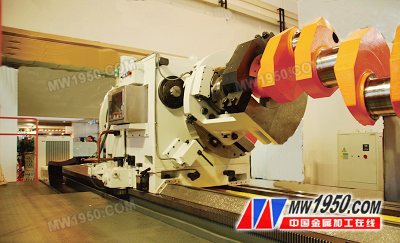
Figure II