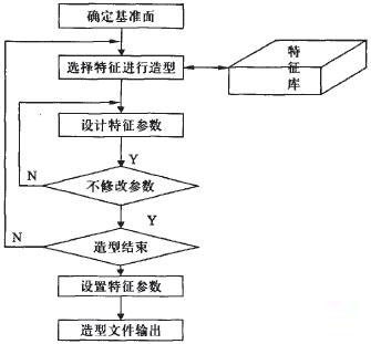
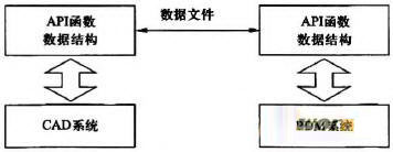
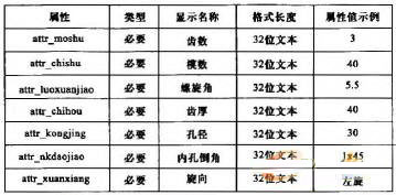
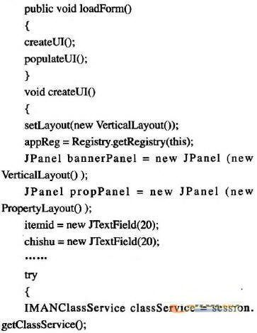
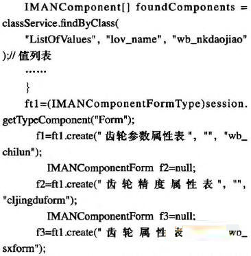
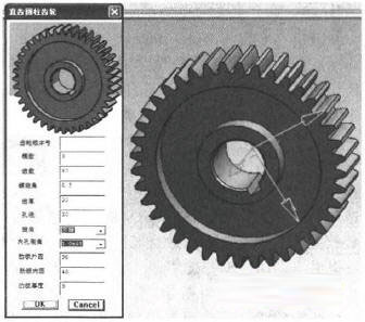
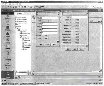
introduction Gear parts are a major part of mechanical transmission. The design and manufacturing level directly affects the performance and quality of mechanical products. The design and manufacture level of gears is also an important indicator of the development level of the national machinery industry. In the face of fierce competition, how to quickly produce parts that meet market requirements is the key to the competition of gear manufacturers, and an effective computer-aided design system is the key to achieve this goal. As a platform for enterprise product development information integration, PDM system can effectively manage the data and documents generated by various software in the product development process by integrating information from different application systems, and realize information sharing between application software. As a three-dimensional CAD software, SolidWorks has three-dimensional modeling of parts, assembly of three-dimensional components, and automatic conversion of three-dimensional solid models into two-dimensional engineering drawings. It is widely used in enterprise product design. In order to provide design data to PDM centralized management, it is necessary to integrate SolidWorks and PDM for SolidWorks users in the enterprise, so that the user's design information can be connected to the PDM end in a timely and unified manner. 1 Feature modeling of gear parts 1.1 The feature model of gear parts and its establishment The difficulty in solving the information integration between CAD and PDM lies in how to accurately and efficiently obtain various product information required for subsequent processing and assembly from the CAD system. Product information is a collection of symbols used to describe or represent attributes related to a product (such as material number, product name, model number, product structure, etc.). The product data model occupies a fundamental position throughout the product-oriented manufacturing process. Under the integration conditions, the data of the product data model in CAD and PDM system should have unique and identical interpretation, and the data model should be globally consistent, so that in the data exchange process, each data can be avoided, misunderstanding and disagreement can be eliminated, and data can be avoided. Redundancy and inconsistency make it possible to manage dynamic data. The product data model includes a structure-oriented product data model, a geometry-oriented product data model, a feature-oriented product data model, and a knowledge-based product data model. The feature-oriented product data model correlates geometric design data with manufacturing data and allows for the design and manufacturing needs to be met simultaneously with a single data structure, making it easy to transfer data between CAD and PDM. Gear type parts are divided into shape features, precision features, assembly features and overall features. The shape feature of the gear part is a basic shape unit with a specific geometry and a specific function formed by a series of geometric elements on the gear part according to a certain topological relationship. According to the different functions of the structural part geometry and the functional requirements of the part, the shape features of the gear type parts can be divided into main features, secondary features and auxiliary features. The main features of a gear-type part are those that describe the basic geometry of the part and that play a major role in the part's routing. It is an independent geometric shape description, which is composed of geometric elements according to certain topological information, such as cylinders, cones and other simple geometric shapes. A minor feature of a gear-type part is a shape feature that is subordinate to a major feature in position and has special processing requirements, such as a keyway on a gear. The auxiliary features of gear parts refer to the local modification and description of the main and secondary features of the subordinates. The auxiliary functions, such as the tooth profile and the tooth profile in the tooth profile, are additional auxiliary features. The gear type part accuracy feature is a collection of information used to describe the dimensional tolerances, geometrical tolerances, and surface roughness of the gears. The precision feature is the main content of the process information. Its description should be related to the main feature, the secondary feature and the related geometric feature of the auxiliary feature, and cannot exist independently from the geometric feature. The general characteristics of the gear parts are a set of information describing the overall characteristics of the gear parts, including part number, part name, blank type, overall size, heat treatment of materials, etc., where the part number is the key to the management of part information and process information; blank Type, overall size, material heat treatment, etc. have different effects on the process route. The classification of gear parts features is shown in Figure 1. Figure 1 Gear parts features 1.2 Characterized feature library for constructing gear parts The current CAD software, the establishment of the feature model is based on the three-dimensional modeling. The starting point of the feature modeling is the geometric model, and the feature itself does not carry the processing technology information (such as dimensional accuracy, shape and position accuracy, surface roughness, etc.). This provides a limited amount of information for the subsequent operations of the part, which is not conducive to product design in a parallel environment. The gear CAD system in this paper uses the integrated method of parameterization and feature mapping to realize the system integration of CAD and PDM. By constructing user-defined features, users can integrate certain model features and process information into parametric parts according to their needs, thus constructing a user-defined feature, and then storing the constructed features in the library by category. Forms a feature library. According to the analysis of gear parts, for the same type of gears, only the adjustment of individual parameters and the characteristic change. The gear is decomposed into several graphic units according to a certain principle, and the design knowledge related to the graphic unit is attached to the graphic unit to form a CAD information model with the graphic unit as the carrier and the characteristic parameters attached. After the parameterized feature library is constructed, the feature parameterization design can be based on this. Feature parametric design allows the designer to use objects that are no longer simple geometric pixels, but feature features and features that carry process information. The modeling process of the parametric features of gear parts is shown in Figure 2. Figure 2 Parametric feature modeling process 2 key technologies and their implementation 2.1 Integration of PDM system and CAD system The integration mode of PDM system and CAD system includes information integration based on STEP standard, information integration based on middleware technology and information integration based on integrated data model. Information integration based on integrated data model is to extract a data model that a system needs to share through the API function and development tool interface provided by the application system, and provide it to another system. The integrated data model is a logical structure representation of data organization in CAD and PDM systems. It is abstracted after reasonable organization of enterprise information. This model provides access to the information needed in CAD and PDM systems. The information integration method using the integrated data model is shown in Figure 3. Figure 3 CAD/PDM integration based on API function calls 2.2 Teamcenter secondary development In this paper, PDM selects the Teamcenter platform of Siemens, and CAD uses the 3D modeling software SolidWorks. Teamcenter's secondary development refers to the use of the integrated development toolkit ITK and C language provided by Teamcenter itself to access the interface of the Teamcenter system, internal objects and their structural relationships for customization. According to the above-mentioned customized content of product characteristics, it is necessary to write a description chart, an inherited or overloaded description chart and explanatory text of various classes, attributes, messages, processes, permissions, and the like. Due to space limitations, only the basic attribute information of gear parts can be listed here. Figure 4 depicts the basic attribute definitions of gear parts. Figure 4 Basic attribute definition of gear parts The code for generating a custom gear class part property sheet is shown below. The gear model based on feature generation and the custom gear class part attribute table are shown in Figures 5 and 6, respectively. Figure 5 Feature-based gear parts Figure 6 Customized gear class part property sheet in the Teamcenter interface 3 Conclusion This paper develops and implements a gear CAD system that generates a feature-based gear model by changing the wheel design parameters on the SolidWorks software platform; realizes the integration of the gear part CAD system with the Teamcenter system: using the SolidWorks software and the secondary development tools provided by the Teamcenter system To realize data exchange and sharing between gear CAD system and Teamcenter. The basic processing parameters required in the process planning process of the gear are stored in the enterprise PDM product database, and the gear parameters in the PDM product database are always consistent with the gear parameters in the CAD system, which is the process automation of the gear processing process and CAPP. A good foundation for integration with PDM.
Space Frame is widely used in all kinds of showroom, coal shed, sport hall roof, etc. which is formed by the main space frame structure, wall and roof using a variety of panels and other components
Space Frame Characteristics:
(1) Wide span: the max span clear distance is 100-150m, without middle column.
(2) Fast construction and easy in installation.
(3) Nice Appearance
Space Frame Space Frame,Space Frame Roofing,Steel Space Frame,Metal Space Frame Shandong Hongtian Heavy Industries Co., Ltd. , http://www.hy-steelbuilding.com