Alumina Ceramic Structural Parts Structural ceramics have superior strength, hardness, insulation, heat conduction, high temperature resistance, oxidation resistance, corrosion resistance, wear resistance, high temperature strength, etc., so they are high in very harsh environments or engineering applications. Stability and excellent mechanical properties have attracted a lot of attention in the material industry, and its use range has been expanding. The global and domestic industries are increasingly demanding high-precision, high-abrasion, high-reliability mechanical components or electronic components. Therefore, the demand for ceramic products is highly valued, and its market growth rate is considerable. Alumina Ceramic Structure Parts ,Alumina Ceramic Parts,Alumina Ceramic Substrate,Alumina Ceramic Dowel Pin Dongguan Haikun New Material Co., Ltd. , https://www.hkceram.com
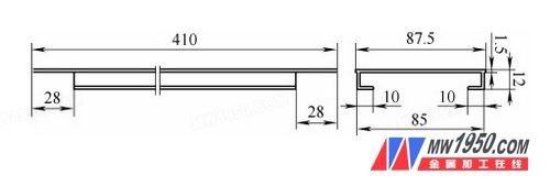
Figure 1
Expand the three-dimensional hanging blank of the machine panel
Figure 1 shows an enlarged machine panel, which was created by cutting a 440 mm section from a formed aluminum profile and then removing the four corners through mechanical processing. The corners that were removed are right-angled and not located on a flat surface, making it difficult to apply traditional methods like sawing or blanking. As a result, conventional techniques often lead to low production efficiency, poor surface quality, and high labor costs.
Using one-time punching would normally be ideal, but due to the complex shape of the part, standard punching is not feasible. Based on the principle of oblique blade blanking, we developed an innovative approach by leveraging the material's own strength and force balance. This allowed us to suspend the workpiece in mid-air, using only a single-sided supported punch die to achieve better part quality.
### Part Analysis
As shown in Figure 1, the four corners of the component have two key characteristics:
1. The area being punched is not on a flat surface, so a standard die cannot be used. Instead, three-dimensional punching is required to remove the corner.
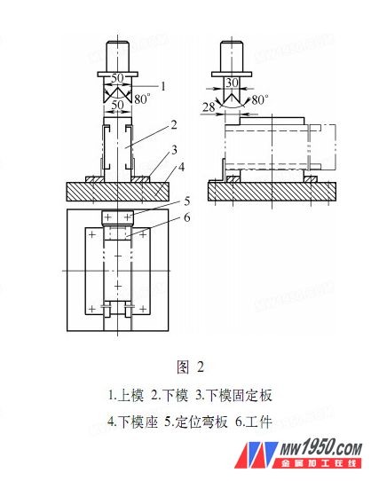
2. Due to its unique shape, the workpiece cannot be supported by a flat lower die. Therefore, the part must extend beyond the lower die during the punching process. This leads to two main requirements: first, the punching force must be less than the deformation resistance of the workpiece to avoid damage. Second, the force applied during the punching of the 10mm portion must be perpendicular to the plane of that section.
### 2. Mold Design
Based on the process analysis and product specifications, we designed the mold as shown in Figure 2. The upper die is structured to reduce the punching force using the principle of oblique edge blanking. The straight edge of 30mm is angled at 40° to 45°, allowing the punch to transition from direct punching to shearing when working on the 28mm side. This reduces the punching force by 5 to 6 times.
On the 50mm side of the upper mold, the punch is aligned parallel to the 10mm section. To ensure proper force direction, we decomposed the force and adjusted the angle accordingly, also designing this edge at 40° to 45°. Additionally, to maintain force balance during the blanking process, we implemented a dual-side punching method. This not only ensures balanced force distribution but also significantly improves production efficiency.
### 3. Precautions in Mold Design
The main challenge in this design was reducing the punching force. The mold must be constructed with as large an angle on the beveled edge as possible, while still maintaining sufficient structural strength to minimize or prevent workpiece deformation during the blanking process. By adding a beveled edge to both sides, a double-beveled structure was achieved, further reducing the required punching force and improving overall performance.