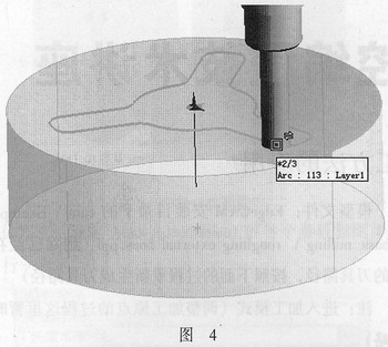
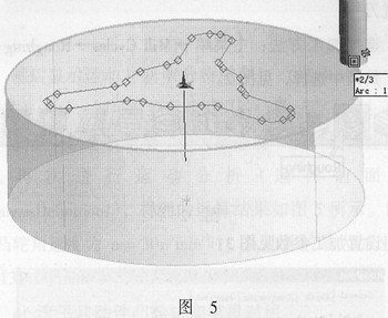
Select the machining object: first select the machining control contour, and double-click to automatically link all the contour lines (by pressing the Tab key during dynamic capture to switch the elements in the mouse cursor range), as shown in Figure 4. After selecting the machining contour, press the right mouse button (or the Enter key) to confirm. Then in the prompt area in the lower left corner of the interface, there is a prompt for Digitise Stock Profile. Then use the left mouse button to pick up the outer blank outline. See Figure 5. After selecting the blank contour and pressing the right mouse button (or the Enter key) to confirm, the prompt area displays: "Digitise containment boundarv entities (Return for none)". This is for you to specify a processing range. In the previous section we specified the machining contour and the blank contour. In addition, we can also select a contour here as the range for generating the machining tool path (independent of the Z plane of the contour). Once a contour is specified, the generated machining tool path is only limited by this contour. Within the scope. If you do not specify a machining range, the resulting tool path is the entire blank area. The machining range is not specified here, so just press the right mouse button (or the Enter key) to confirm. Previous Next Self Balance Scooter,Electric Scooter,2 Wheels Unicycle Simple Shower Room Co., Ltd. , http://www.chinaatvpart.com
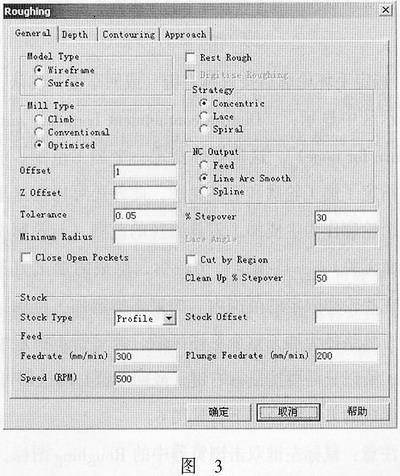
Set processing parameters as shown in Figure 3: